<br>
#### Week 3: Stormy Seas
[kinetic sculpture project]
<img width="600px" height="300px" src="ks2.gif">
<span>This week was hard! My first attempt failed completely and my second one has a lot of room for improvement. But I certainly learned a lot and I'm looking forward to continuing to tweak this design.</span>
<span>the idea</span>
I love the movement of the ocean so it felt right to dedicate my kinetic sculpture to capturing it. Being away from home I really miss not being able to see it everyday. My general idea was to create a 4 part cam system, contained by an open-sided box, which would move three waves and a fish about 1 inch up and down. The design did not work on the first try and even my second attempt is very far from perfect. But it's moving and I’m really glad to have gotten it to this point!
<span>the first iteration</span>
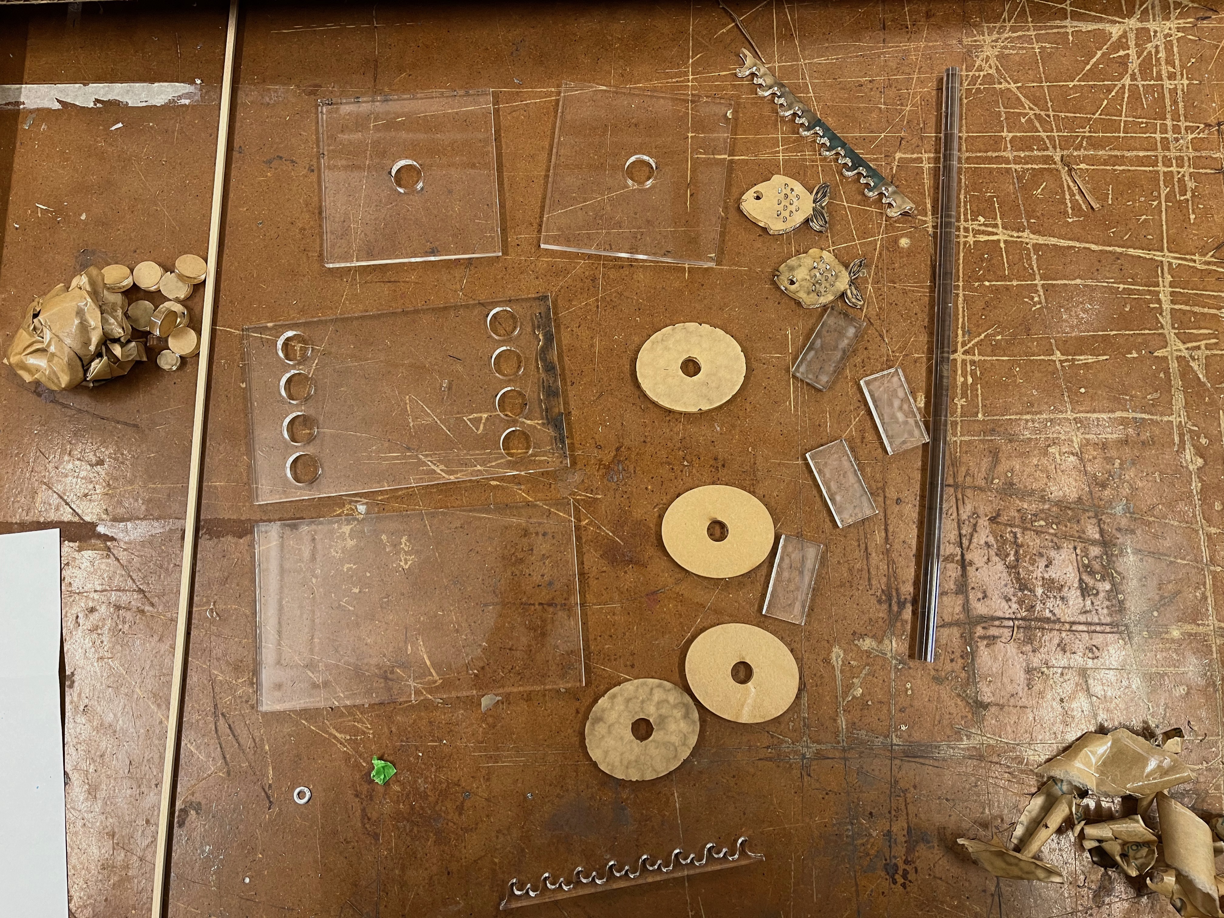
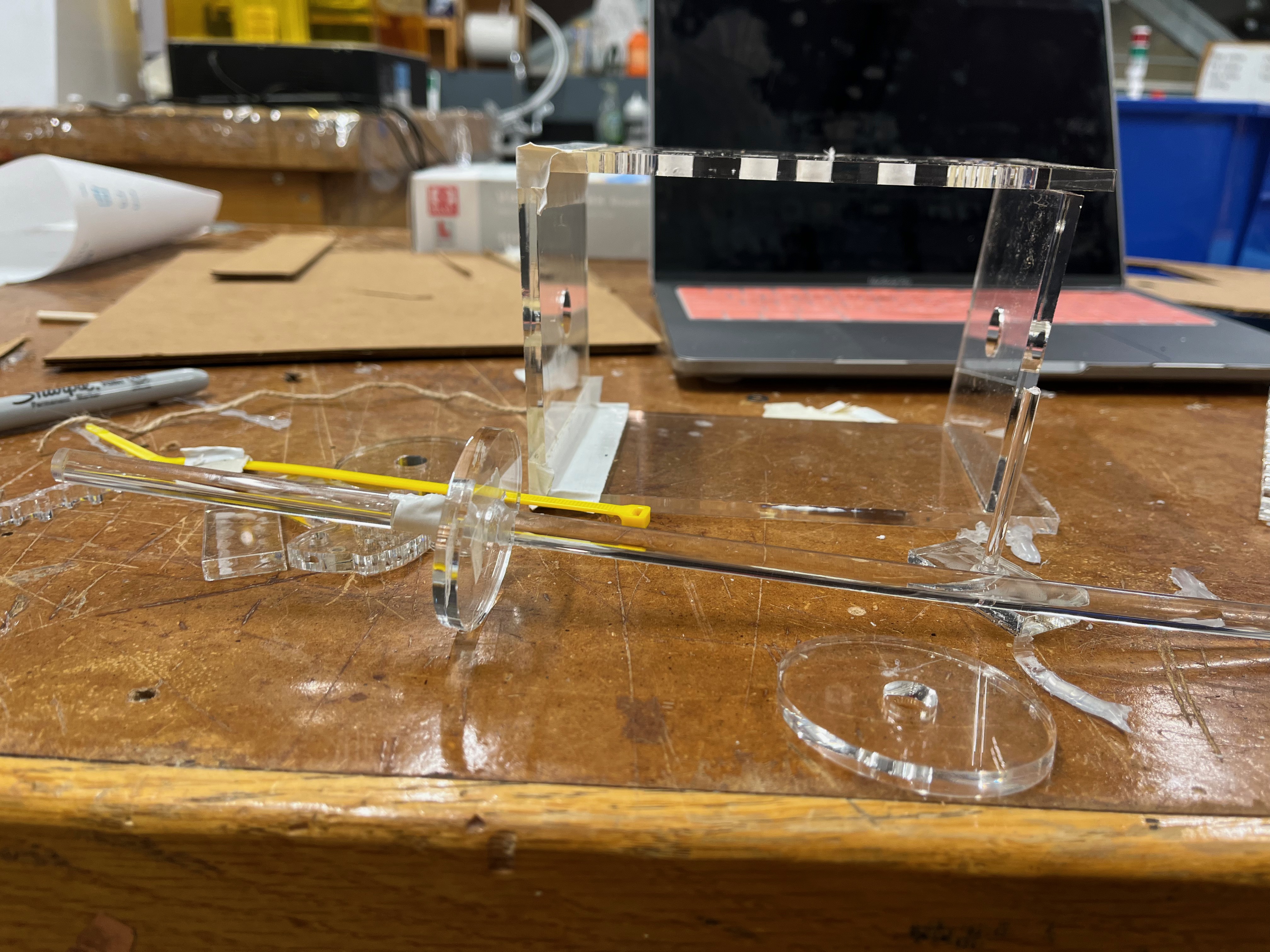
The first iteration of Stormy Seas was constructed from pieces which I designed on Fusion360, laser cut on clear acrylic, and assembled using hot glue and duct tape. Ultimately, I found that the acrylic was extremely slippery and heavy; without pressfit notches, the box was really hard to hold together. Hot glue also peeled off the acrylic easily, so none of my joints were sound. The duct tape helped, and perhaps I would have stuck it out but I soon found a second failure of my system— the holes I had cut in the top of the box to allow for the cams and decorative pieces to be connected were awkwardly spaced. I quickly (and sadly) realized that this would make it essentially impossible for the cam to move smoothly if I retained this configuration. And though I tried to recut the holes on the original pieces of acrylic, I decided it would be neater to start from scratch. Below are some photos of the failed design to help you visualize it better. I’m not going to go into the nitty gritty of the dimensions/assembly process, as I altered them in the improved second design.
<span>the second iteration</span>
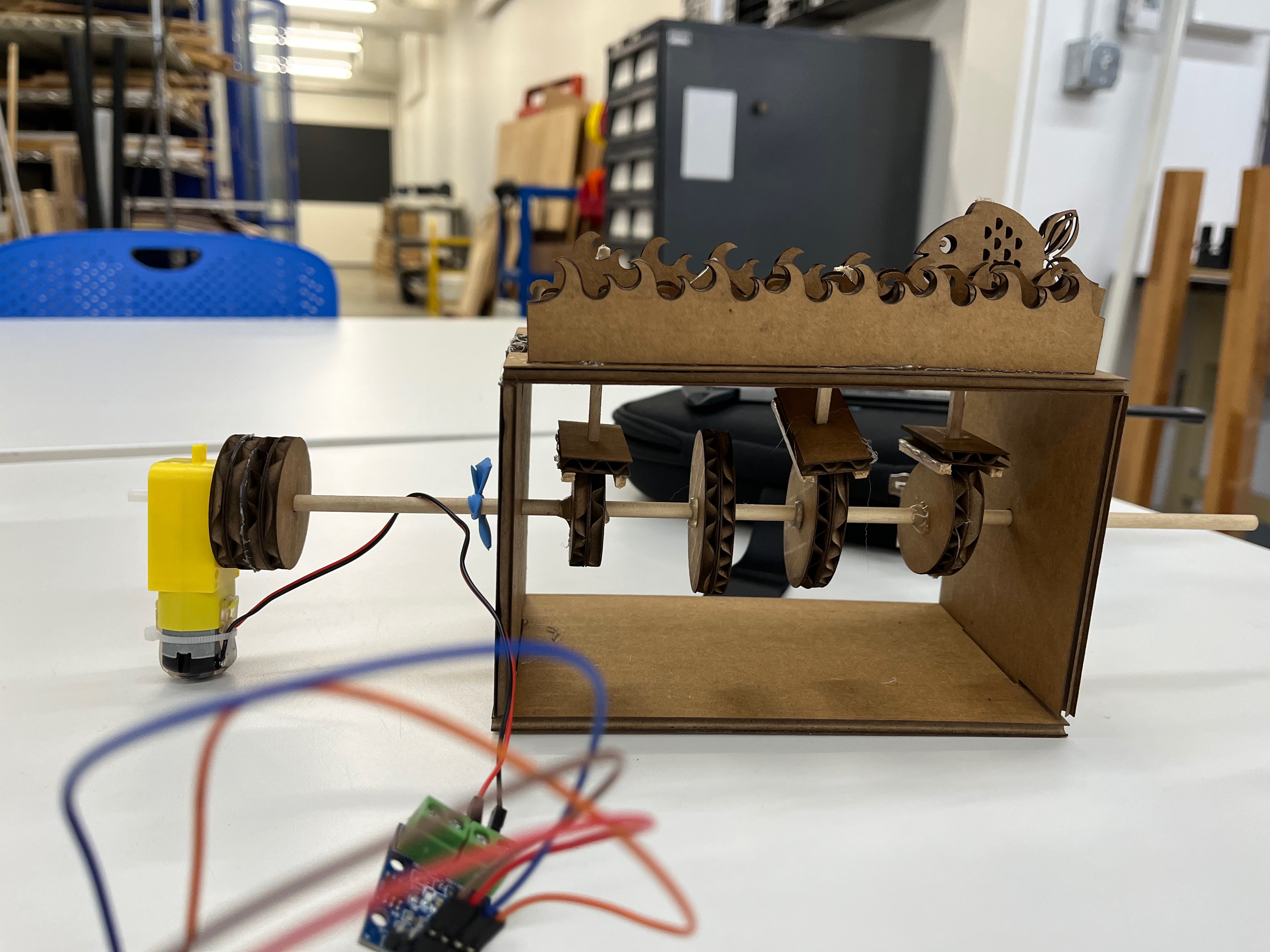
The second iteration of Stormy Seas was constructed from cardboard, with press fit notches added to the box and better positioned connector holes! I’ve broken down my explanation of how it built it into chunks based on the major parts.
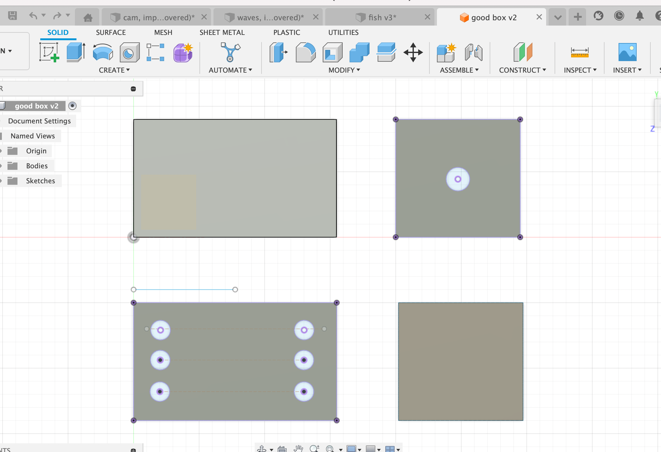
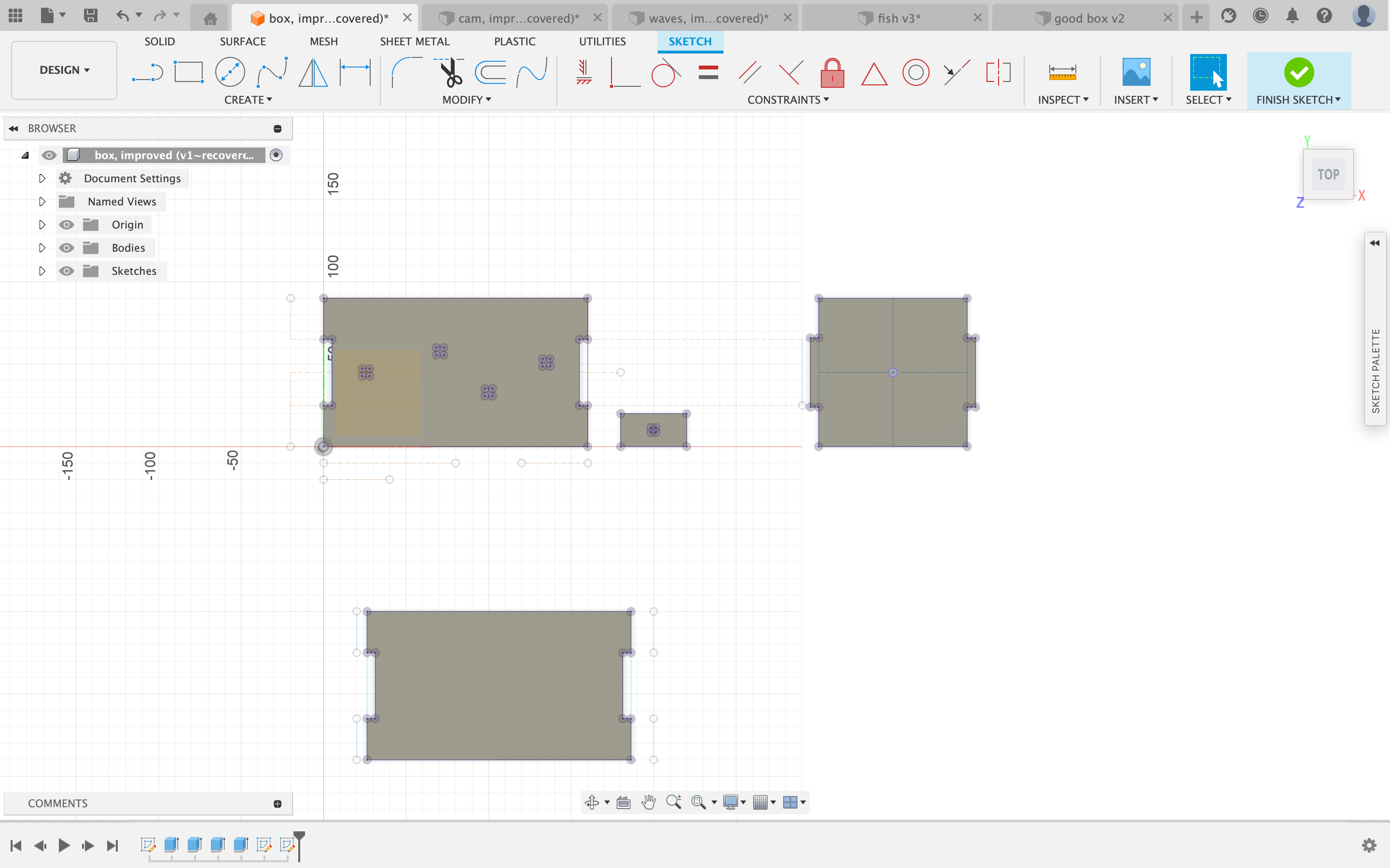
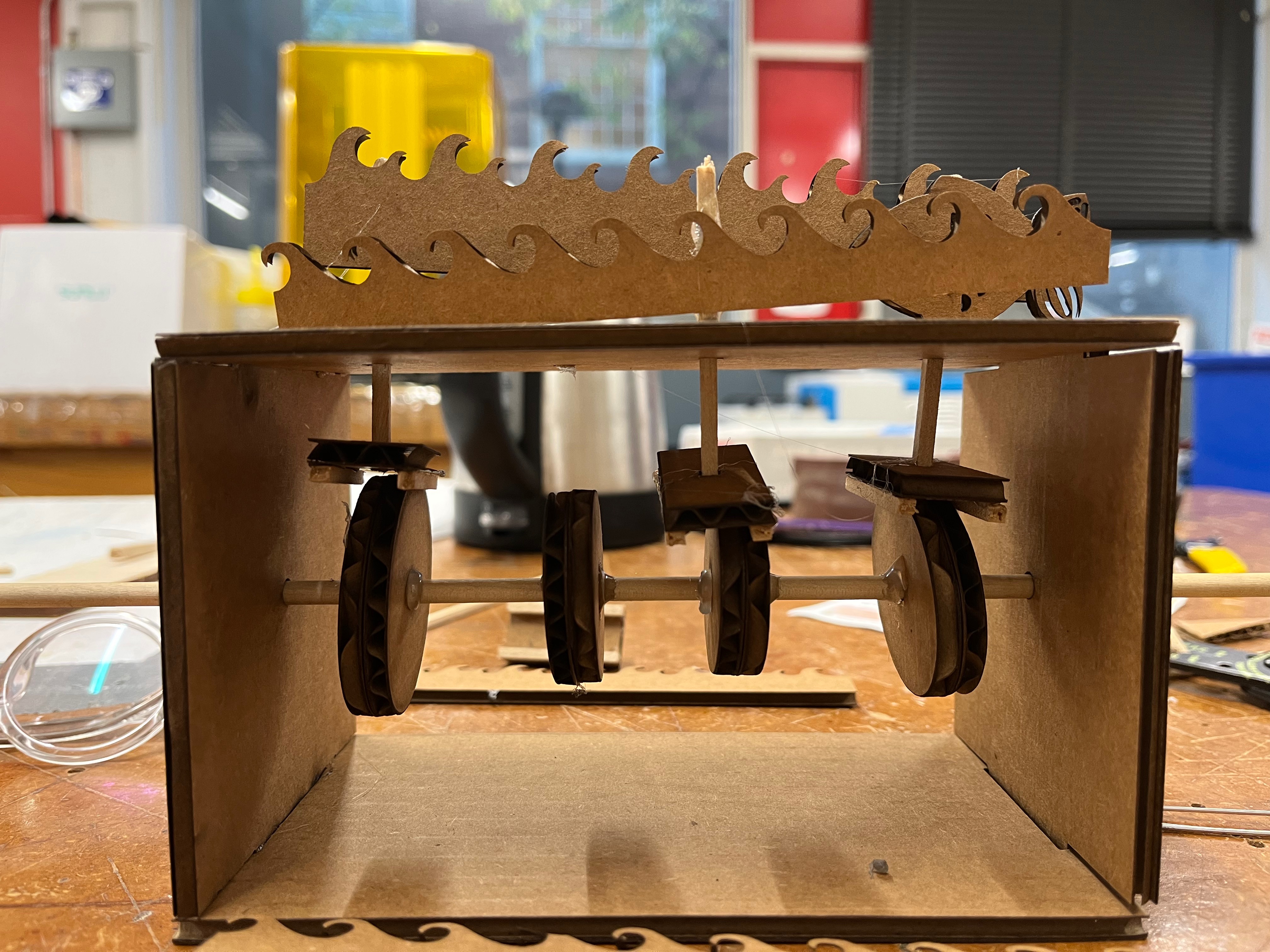
<span>the box & cam system</span>
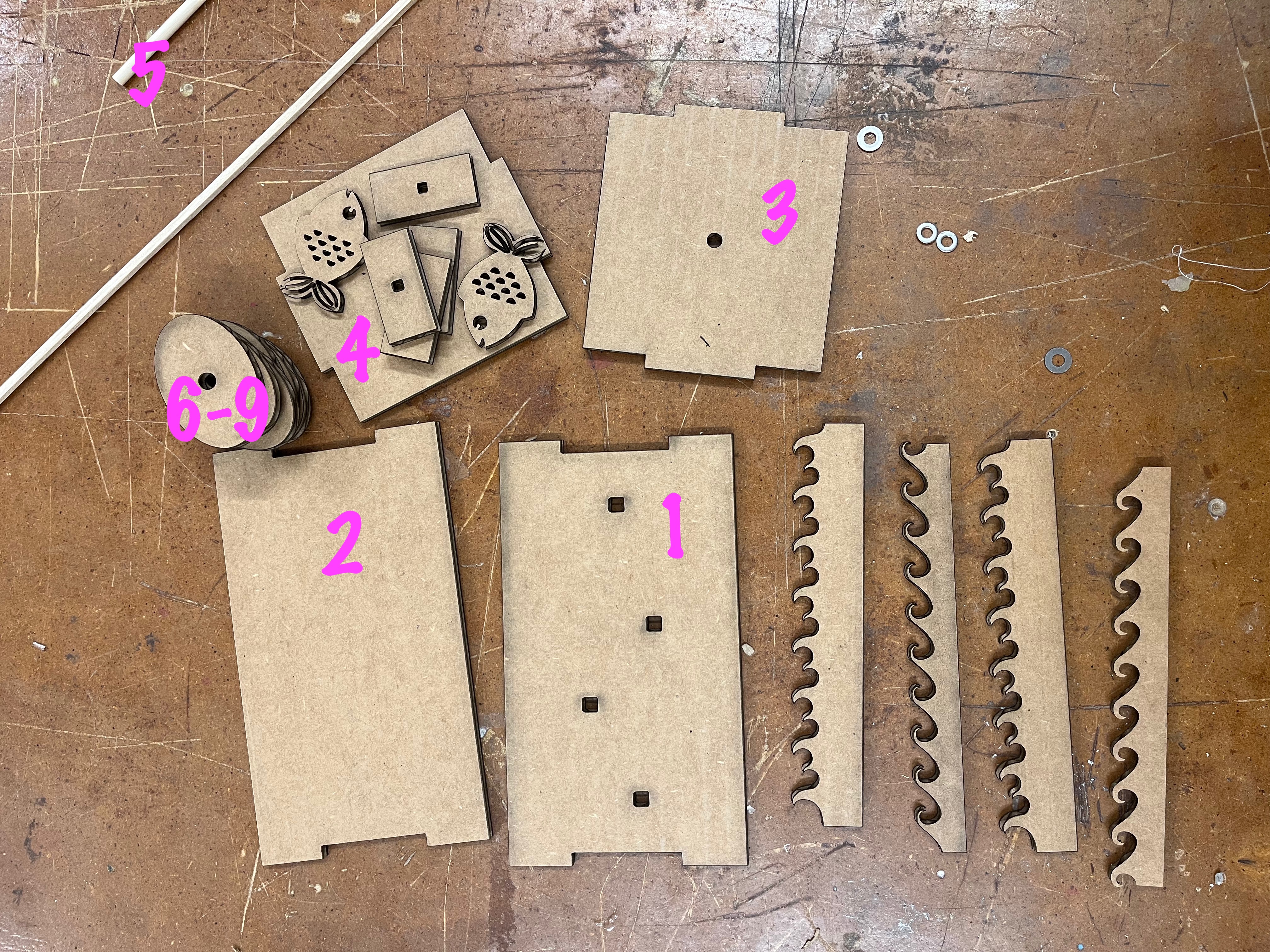
The box was simply 2 long and 2 short rectangular faces (dimensions: 90mm by 155mm and 90mm by 90mm respectively). The long faces had rectangular tabs (dimension: 40mm by 4mm) while the short ones had rectangular notches (dimension: 42mm by 5.05mm), which created a pressfit system. The 2 short faces had circular holes (dimension: 5mm diameter) in the center to hold a wooden dowel (dimension: 4mm diameter) to which I would eventually affix four cams. The cams were ellipses (dimensions: 136.20mm at longest point by 35.83mm at the widest point). They also had circular holes (5mm diameter) for the dowel. One of the long faces had square holes at irregular intervals, which would eventually allow me to connect the decorative pieces (fish, waves) to the cams. See below for photos of these parts individually and partially assembled. From here onward I’ll refer to parts by their numbers to keep my explanation succinct.
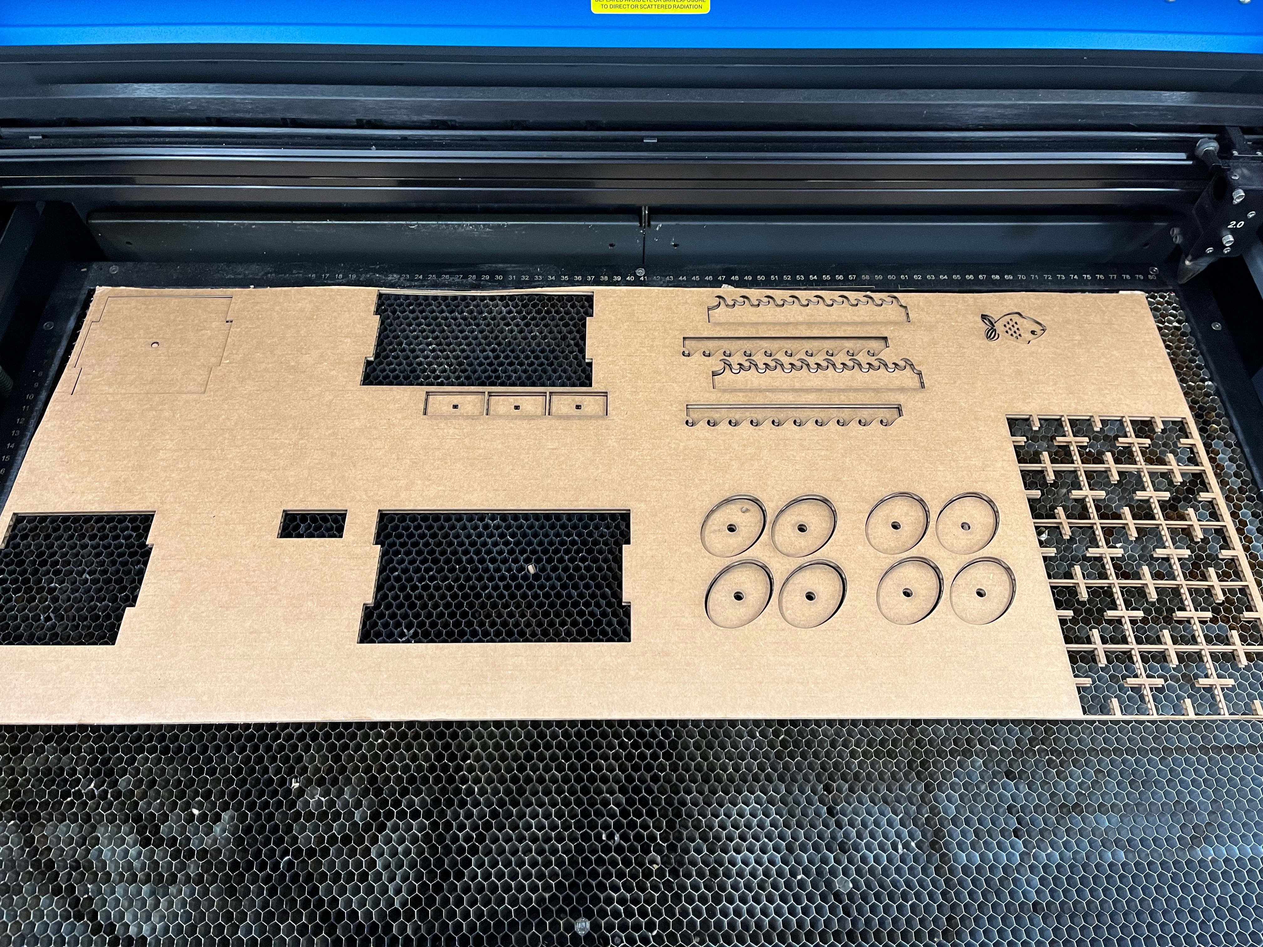
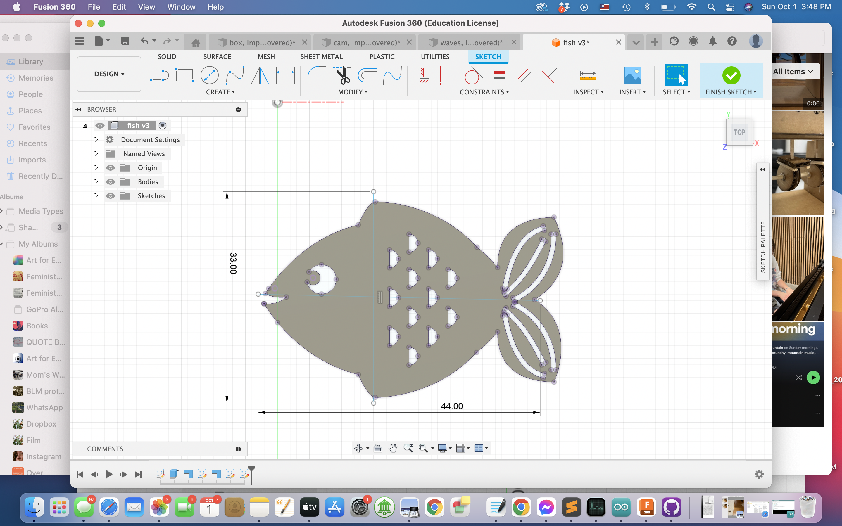
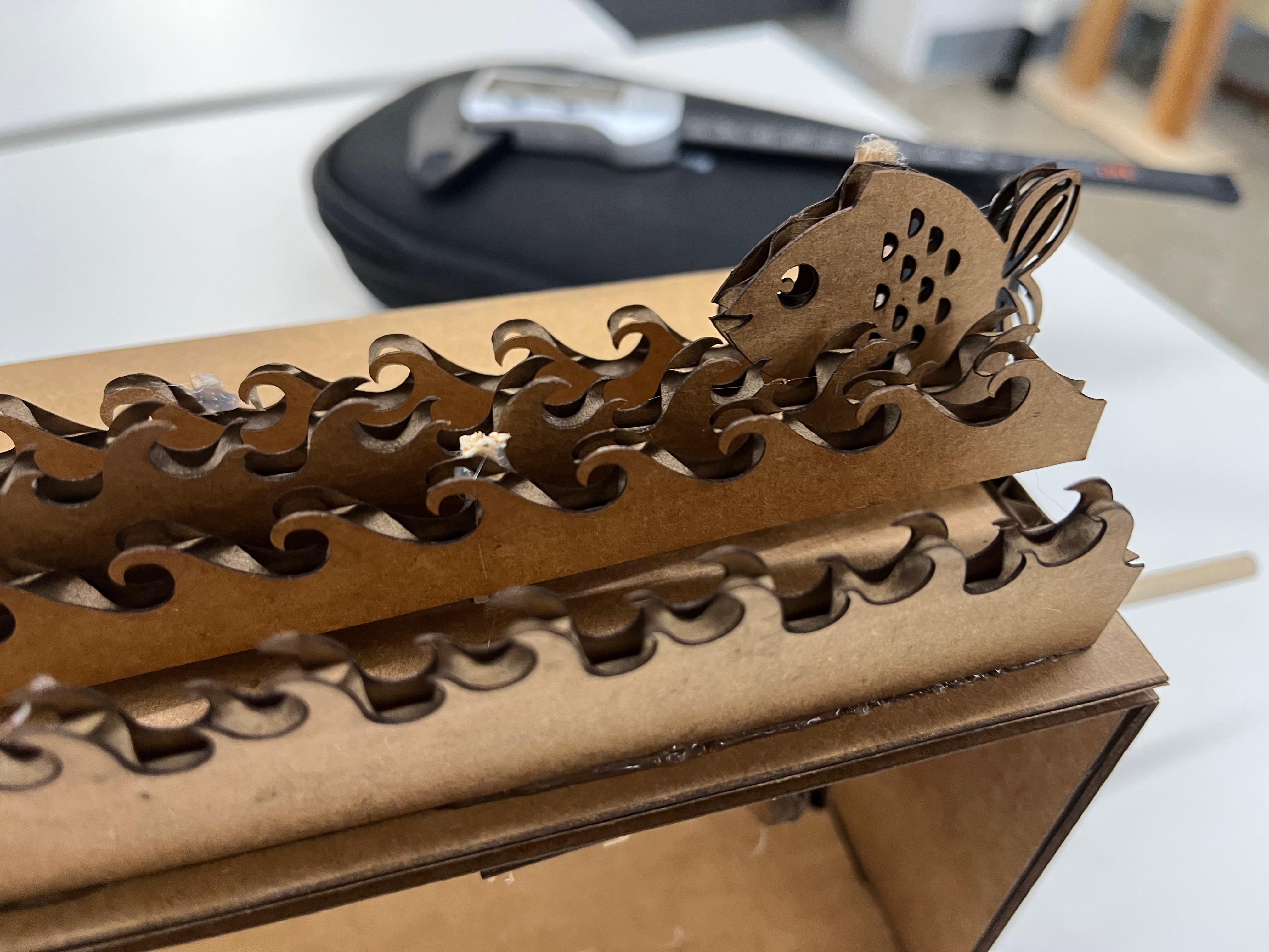
<span>the waves & fish</span>
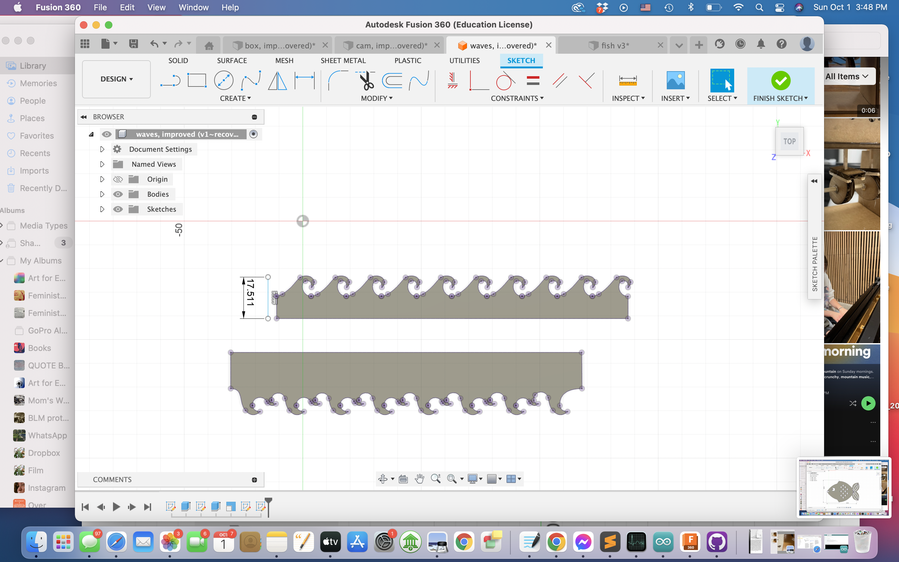
The waves (dimensions: approx 148.27mm by 17.51mm) and fish (dimensions: approx 44mm by 33mm) both came from vector images. I found them for free on the internet and edited them in Fusion360.
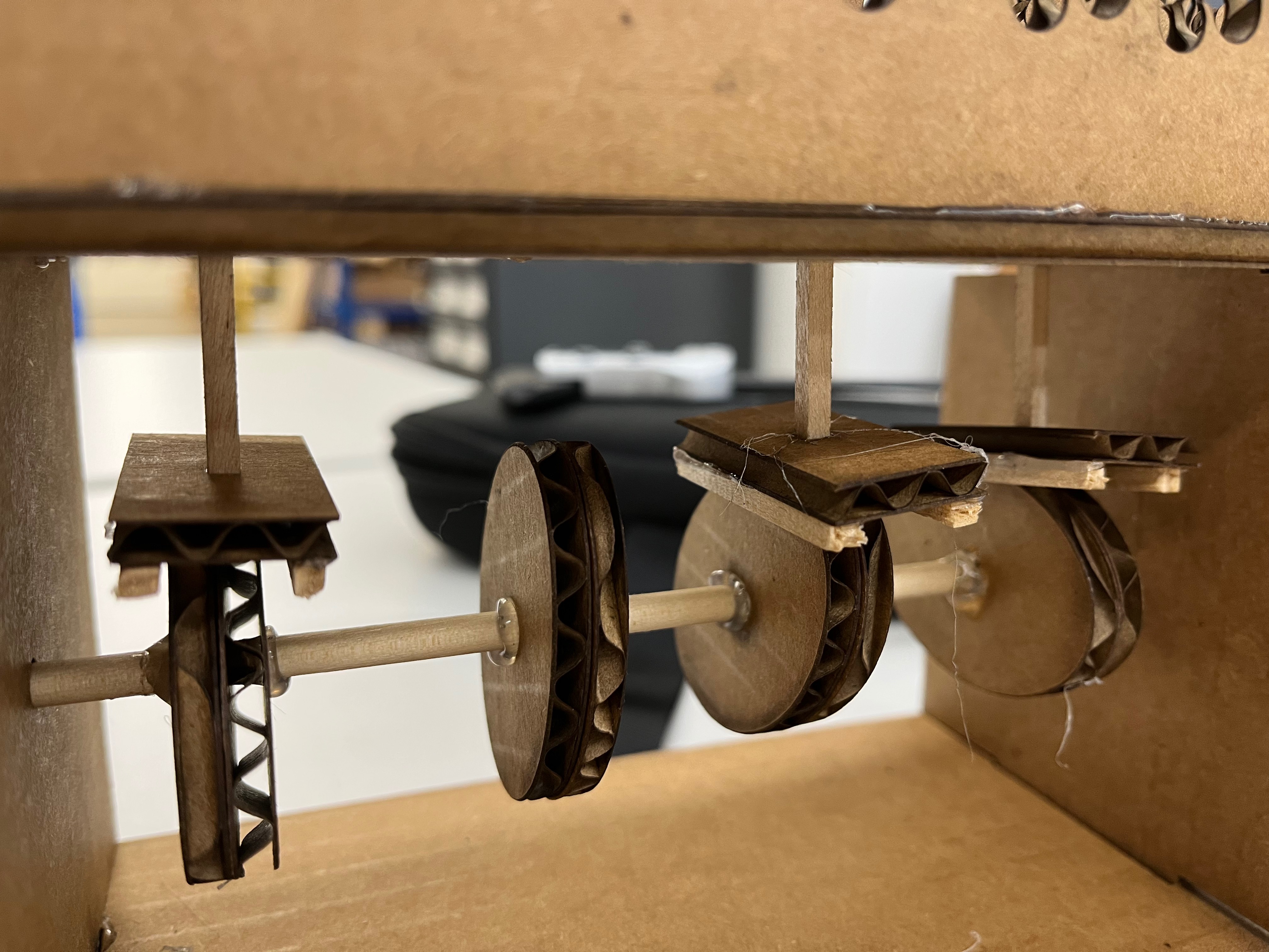
<span>the cam connection system</span>
A key piece of this design is how to transfer the movement of the cams to the fish and waves. If this is not done successfully, there will be no kinetic element! To make this connection I laser cut a few rectangles (dimensions: 40mm by 20mm) with square holes (dimension: 2.95mm by 2.95mm) in the center. Into these holes I then inserted a small square dowel (dimensions: 3mm by 3mm) to create a T-shape. The cardboard would eventually rest on top of each cam, bobbing up and down freely with their motion. The wooden dowels would extend up through the holes in piece one with their tips attached to each decorative piece. In this way, the motion of the cams would be transferred to the decorative pieces. After some trial and error I found that the cardboard sometimes slips off the cams, so I added small wooden rails to the bottom of each connector. This makes sure the connectors stay in contact with the cams and do not twist.
<span>1st round of assembly</span>
I think a list of steps will serve best to describe assembly!
1. Hot glue three sides of the box together (pieces 1-3) to create U-shape.
2. Glue all cams to large circular wooden dowel (pieces 5-9) , spaced at intervals that match the spaces between the holes on piece 1.
3. Be sure the cams are glued at different angles to ensure that the fish and waves don’t move in unison.
4. Insert one end of this dowel into the hole in piece 2, let the other end rest on the table.
5. Collect T-shaped connector pieces and place the cardboard side on the top of each cam. Be sure each small square dowel extends up through a hole in piece 1.
6. Hot glue waves and fish to the tops of exposed dowels.
7. Complete the box by attaching piece 4.
8. Stop the large dowel from sliding back and forth by adding a brake. A rubber band looped a few times around the dowel immediately before it enters the box would be ideal. I couldn’t find a rubber band so I made one by cutting up an uninflated balloon.
9. Voilà! You now have a kinetic sculpture that can be activated by manually spinning the large dowel.
<span>the motor & connector system</span>
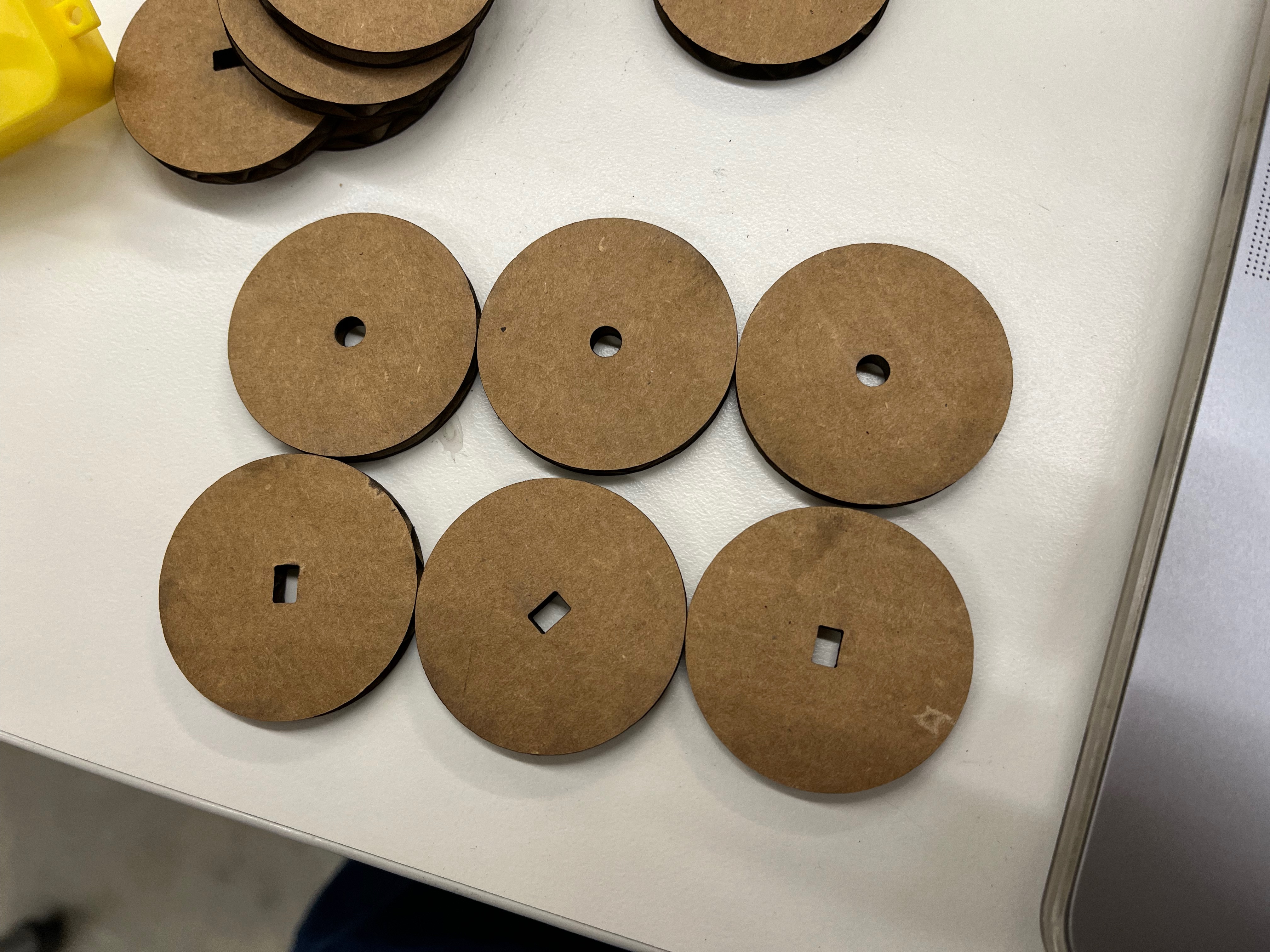
After I assembled the majority of my sculpture the next challenge was attaching the motor. Shoutout to Bobby for helping come up with this idea! Bobby is awesome! My motor attachment consists of 4 circular cardboard cutouts (dimension: approx 40mm diameter). 2 these circles have a circular hole in the center (dimension: 4.8mm diameter) and 2 have a rectangular hole (dimensions: approx 3.8mm by 1.8mm). The rectangular hole can be pressfit to the rotating extension of the motor while the circular hole can be pressfit to the large dowel. When all 4 circles are glued together, they create a piece that connects the dowel and the motor.
<span>the Arduino programming</span>
I used the potentiometer code on the PS70 site. Thanks to Bobby for helping me debug and explaining to me how it worked!
2nd round of assembly:
<span>notes for the third iteration</span>
While this second iteration works much better than the first, there’s still a ton of room for improvement. Most notably, the sculpture can only move with the motor for a couple of seconds before getting stuck; the cam system should be adjusted so that the T-shaped connectors do not snag on the cams. Additionally, the waves and fish are a little too heavy for the small dowels and they hang off at a bit of an angle. And the cams are not quite long enough, so the height differential that creates movement is not as drastic as I had hoped.
Fish and wave designs courtesy of: <a href="https://www.freepik.com/free-vector/set-colorful-fishes-flat-style_2111527.htm#query=fish&position=18&from_view=search&track=sph#position=18&query=fish">Freepik</a> and <a href="https://www.freepik.com/free-vector/set-colorful-fishes-flat-style_2111527.htm#query=fish&position=18&from_view=search&track=sph#position=18&query=fish">Freepik</a>